Snaky CCC tunnel
Edoardo
Martelli, CERN IT-CS-EN,
24 August 2004
Abstract
This document describes how a CCC
tunnel was created stitching together several pairs of LSPs
defined on the same physical link. This was tested in order to
artificially
increase the round trip time and verify the TCP behaviour over a very
long distance.
Table of Contents
The snaky CCC tunnel
Bandwidth considerations
Performance tests
Configurations
ar5-chicago
cernh5
The snaky CCC tunnel
In order to artificially increase the round trip time of a connection,
it was configured a CCC (Circuit Cross Connection) tunnel that used two
sets of LSPs (Link State Path), appropriately stitched together.
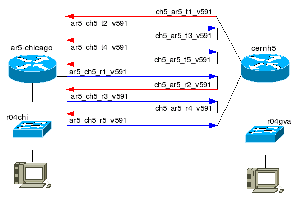
The following picture describes the set-up:

The five red arrows depict the LSPs defined on the Juniper router
cernh5. They were essentially the same, only the names were different.
The five blue arrows depict the LSPs defined on the Juniper router
ar5-chicago. A CCC tunnel needs one transmit LSP and one receive LSP;
in order to have an IP packet going back and forward on the same link,
couple of basic LSPs were stitched together. The configurations tested
had two, three and five basic LSPs in each bigger LSP, but this
document describe only the five basic LSPs configuration.
Bandwidth considerations
This exercise allows to increase the round trip time of a connection.
But since the bandwidth is a finite resource, it decreases with the
growing of number of LSPs used.
The full duplex bandwidth can be calculated in this way: Link Bandwidth / (total #of LSPs / 2)
In this case, the full duplex bandwidth available was: 10Gbps /
(10 / 2) = 2Gbps
To calculate the half-duplex bandwidth, it should be considered the
basic LSPs used for the used LSP, and divide the link bandwidth for the
greater number of basic LSPs defined on the same direction.
In this case, the half duplex bandwidth available was: 10Gbps / 3 =
3.3Gbps
Performance tests
The snaky CCC tunnel was tested over the DataTAG/LHCnet transatlantic
STM64 link. The round trip time is 116ms and with this configuration it
became 581ms, almost exactly 5 times 116:
R04gva#ping 192.91.239.56
Sending 5, 100-byte ICMP Echos to
192.91.239.56, timeout is 2 seconds:
!!!!!
Success rate is 100 percent
(5/5), round-trip min/avg/max = 116/116/116 ms
R04gva#ping 192.91.238.61
Sending 5, 100-byte ICMP Echos to
192.91.238.61, timeout is 2 seconds:
!!!!!
Success rate is 100 percent
(5/5), round-trip min/avg/max = 580/581/584 ms
UDP and TCP tests were running using iperf on a couple
workstations with 1Gbps ethernet interfaces.
TCP was stable at 990Mbps using a window size of 64MBytes.
[root@w05gva emartell]# iperf -i
2 -f m -m -t 300 -w 64M -c 192.91.238.51
[ 5] 0.0-300.7
sec 34624 MBytes 966 Mbits/sec
[ 5] MSS size 8948 bytes
(MTU 8988 bytes, unknown interface)
[root@w05chi emartell]# ./iperf
-s -w 64M -i 2
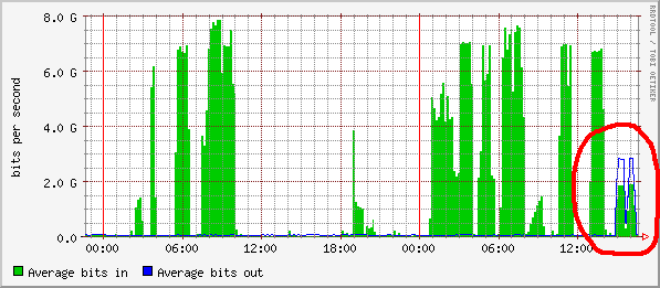
The stream was 1G in a single direction, and this graph shows the
asymmetry due to the odd number of LSPs involved in each direction:

Here follows some settings of the end hosts used to generate the 1G
stream:
ifconfig eth0 mtu 9000 txqueuelen
50000
echo "4096 87380 128388607" > /proc/sys/net/ipv4/tcp_rmem
echo "4096 65530 128388607" >
/proc/sys/net/ipv4/tcp_wmem
echo 128388607 >
/proc/sys/net/core/wmem_max
echo 128388607 >
/proc/sys/net/core/rmem_max
Configurations
Here the configurations of the two Juniper routers.
ar5-chicago
interfaces {
so-1/0/0 {
unit 0 {
family inet {
address 192.65.184.53/30;
}
family mpls {
mtu 9188;
}
}
}
ge-1/1/0
{
vlan-tagging;
encapsulation vlan-ccc;
unit 591 {
encapsulation vlan-ccc;
vlan-id 591;
family ccc;
}
}
}
protocols {
rsvp {
interface all;
}
mpls {
explicit-null;
label-switched-path ar5_ch5_t2_v591 {
from 192.65.184.53;
to 192.65.184.54;
no-cspf;
}
label-switched-path ar5_ch5_t4_v591 {
from 192.65.184.53;
to 192.65.184.54;
no-cspf;
}
label-switched-path ar5_ch5_r1_v591 {
from 192.65.184.53;
to 192.65.184.54;
no-cspf;
}
label-switched-path ar5_ch5_r3_v591 {
from 192.65.184.53;
to 192.65.184.54;
no-cspf;
}
label-switched-path ar5_ch5_r5_v591 {
from 192.65.184.53;
to 192.65.184.54;
no-cspf;
}
interface all;
}
connections {
remote-interface-switch ccc_snaky_v591 {
interface ge-1/1/0.591;
transmit-lsp ar5_ch5_r1_v591;
receive-lsp ch5_ar5_t5_v591;
}
lsp-switch ar5_t_1_2 {
transmit-lsp ar5_ch5_t2_v591;
receive-lsp ch5_ar5_t1_v591;
}
lsp-switch ar5_t_3_4 {
transmit-lsp ar5_ch5_t4_v591;
receive-lsp ch5_ar5_t3_v591;
}
lsp-switch ar5_r_2_3 {
transmit-lsp ar5_ch5_r3_v591;
receive-lsp ch5_ar5_r2_v591;
}
lsp-switch ar5_r_4_5 {
transmit-lsp ar5_ch5_r5_v591;
receive-lsp ch5_ar5_r4_v591;
}
}
}
cernh5
interfaces {
so-1/0/0 {
unit 0 {
family inet {
address 192.65.184.54/30;
}
family mpls {
}
}
}
ge-1/1/0 {
vlan-tagging;
encapsulation vlan-ccc;
unit 591 {
description "----> snaky CCC";
encapsulation vlan-ccc;
vlan-id 591;
family ccc;
}
}
}
protocols {
rsvp {
interface all;
}
mpls {
explicit-null;
label-switched-path ch5_ar5_t1_v591 {
from 192.65.184.54;
to 192.65.184.53;
no-cspf;
}
label-switched-path ch5_ar5_t3_v591 {
from 192.65.184.54;
to 192.65.184.53;
no-cspf;
}
label-switched-path ch5_ar5_t5_v591 {
from 192.65.184.54;
to 192.65.184.53;
no-cspf;
}
label-switched-path ch5_ar5_r2_v591 {
from 192.65.184.54;
to 192.65.184.53;
no-cspf;
}
label-switched-path ch5_ar5_r4_v591 {
from 192.65.184.54;
to 192.65.184.53;
no-cspf;
}
interface all;
}
connections {
remote-interface-switch ccc_snaky_v591 {
interface ge-1/1/0.591;
transmit-lsp ch5_ar5_t1_v591;
receive-lsp ar5_ch5_r5_v591;
}
lsp-switch ch5_t_2_3 {
transmit-lsp ch5_ar5_t3_v591;
receive-lsp ar5_ch5_t2_v591;
}
lsp-switch ch5_t_4_5 {
transmit-lsp ch5_ar5_t5_v591;
receive-lsp ar5_ch5_t4_v591;
}
lsp-switch ch5_r_1_2 {
transmit-lsp ch5_ar5_r2_v591;
receive-lsp ar5_ch5_r1_v591;
}
lsp-switch ch5_r_3_4 {
transmit-lsp ch5_ar5_r4_v591;
receive-lsp ar5_ch5_r3_v591;
}
}
}
back to the top


